Pages

Subscribe:
Showing posts with label Signalling. Show all posts

A Look into 5G Virtual/Open RAN - Part 1

Although it is understood in general that virtualization and increasing complexity are inherent characteristics of 5G networks many people are surprised when they realize the significant differences of 5G RAN architecture and signaling procedures compared to what they know from LTE or UTRAN.

In this blog post series I want to highlight some details that are not immediately visible when reading the 3GPP specs.

Figure 1 shows a virtualized gNB and the protocols it uses to communicate with its internal entities as well as with the UE and peer entities in neighbor network elements/functions.

Figure 1: Virtual Network Functions and Protocols in 5G RAN
(click on the image to see full size)

The core of the whole thing is the gNB-Central Unit for the Control Plane (gNB-CU CP). This function communicates directly with the UE using the NR RRC protocol. It also "talks" to the 5G Core Network represented by the AMF using the NGAP, a protocol very similar to the S1AP known from E-UTRAN. Neighboring 5G base stations are contacted using the XnAP, neighboring eNBs can be reached by using X2AP.

The other virtual functions of the gNB are the Central Units for User Plane (gNB-CU UP) and the Distributed Units (gNB-DU). While the gNB-CU UP is responsible for handling the transport of payload the gNB-DUs deal with all the allocation of radio resources, especially the scheduling. As a result the lower layer radio interface protocols, especially RLC and MAC terminate in the gNB-DUs.

For the RAN monitoring tools and the 3GPP Minimization of Drive Test (MDT) feature this means that RRC and Logged Measurement Reports sent by UEs will be available at gN-CU CP while all uplink radio quality measurements and call-related user plane metrics is only available at the gNB-DU - see figure 3.

Figure 2: Distribution of un-correlated RAN measurement tasks among different gNB virtual functions
(click on the image to see full size) 

And today, there is no 3GPP-standardized procedure to correlate this measurement information collected by different virtual gNB functions.

The full impact of the 5G RAN virtualization becomes even more evident when looking at Figure 3. It shows a single gNB-CU CP in charge of controlling several gNB-CU UPs and gNB-DUs.

In a live network deployment a single gNB-CU CP will control hundreds of gNB-DUs and maybe several gNB-CU UPs. This is why it is misleading to compare the connectivity of a gNB-CU CP with that of a LTE eNB. Rather it could be compared with a UTRAN RNC controlling a similar number of 3G base stations.


Figure 3: 5G RAN Connectivity
(click on the image to see full size)

Looking back into figure 1 we see that the F1AP is used for communication between gNB-CU CP and its gNB-DUs while the E1AP is the protocol that connects the gNB-CU CP with surrounding gNB-CU UPs.

Call-related control plane procedures of F1AP and E1AP are very similar to what is known from NGAP. There is a UE context established between the gNB-CU CP and the gNB-DU. On F1-U a GTP tunnel is established for user plane transport. At the same time an E1 Bearer Context in gNB-CU CP and gNB-CU UP keeps track of the most relevant user plane transport parameters.

All in all for setting up a single subscriber connection in the virtualized 5G RAN there are significantly more signaling transactions necessary than in E-UTRAN. Figure 4 shows a practical example.

Figure 4: 5G RAN Call Trace in NETSCOUT Session Analyzer
(click on the image to see full size)
The volume and complexity of signaling information is increasing when the UE moves or is redirected to virtual functions within one gNB e.g. due to load balancing.

The next blog post of this series will dive deeper into details of such call scenarios.

Stay tuned...
EPS Fallback in 5G Standalone Deployments

It can be expected that later this year some mobile network operators will launch their initial 5G standalone (5G SA) deployments.

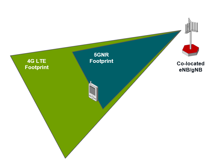
Nevertheless there will remain areas with temporary or permanently weak 5G NR coverage. One possible reason might be that even when 5G and LTE antennas are co-located, which means: mounted at the same remote radio head, the footprint of the 5G NR cell is significantly smaller when it uses a higher frequency band than LTE - see figure 1.

Figure 1: Smaller footprint of co-located 5G NR cell with higher frequency
Especially UEs making Voice over New Radio (VoNR) calls from the 5G cell edge have a high risk of experiencing bad call quality, in worst case a call drop. To prevent this the UE is forced  during the voice call setup towards 5G core network (5GC) to switch to a LTE/EPS connection where the radio conditions are better for the voice service.

The same procedure for which the term "EPS Fallback" was coined by 3GPP also applies when the UE is served by a 5G cell that is not configured/not optimized for VoNR calls or when the UE does not have all needed VoNR capabilities.

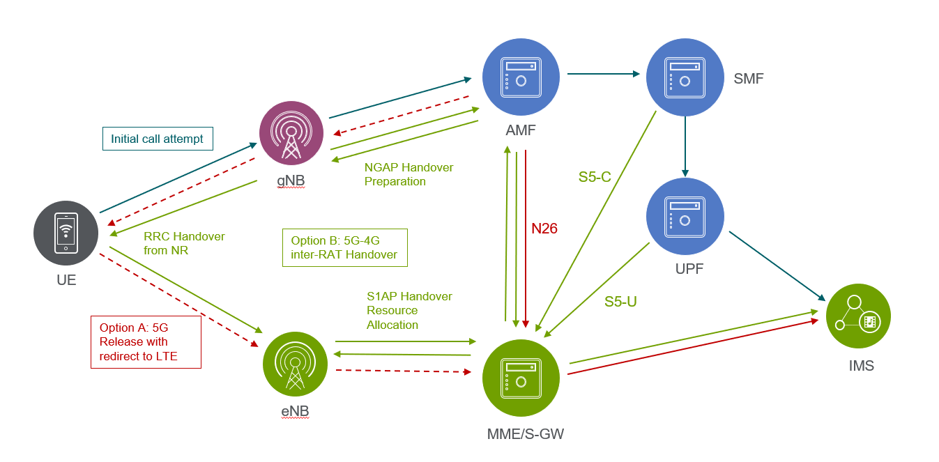
Figure 2: Two options for EPS fallback

When looking at the RAN there are two options for executing the EPS Fallback as shown in figure 2.

In option A the 5G radio connection is released after the initial call attempt is successfully finished and with the 5G RRC Release the UE is ordered to reselect to a 4G cell where a new radio connection is started for the VoLTE call. In this case the UE context is transferred from the AMF to the MME over the N26 interface. 3GPP seems to use also the term "RAT fallback" for this option.

Option B is to perform a 5G-4G inter-RAT handover. Here the session management and user plane tunnels in the core network are handed over from SMF/UPF to MME/S-GW in addition. This is realized with the GTPv2 Forward Relocation procedure on N26 interface.

All in all the EPS fallback is expected to cause an additional call setup delay of approximately 2 seconds.

For the inter-RAT handover case it is easy to detect from signaling information that an EPS fallback was triggered. In the source-eNodeB-to-target-eNodeB-transparent-container sent by the gNB to the eNB a boolean "IMS voice EPS fallback from 5G" indicator will be found that is set to "true". This container is named according to the receiving entity and will be carried by the NGAP Handover Preparation, GTPv2 Forward Relocation Request and the S1AP Handover Request messages.

If a redirection for Voice EPS Fallback is possible or not is indicated in the NGAP Initial Context Setup Request, Handover Request (during 5G intra-system handover) and Path Switch Request Acknowledge (after Xn handover) messages, all sent by the AMF to the gNB.

Further the NGAP protocol provides the cause value "IMS voice EPS fallback or RAT fallback triggered" in the PDU Session Resource Modify Response message indicating that a requested VoNR session cannot be established.  


How MOCN RAN-Sharing Works


Shared RAN deployment scenarios are an excellent opportunity for mobile network operators to lower their investments on both, network hardware and operational costs by sharing resources.

The MORAN approach where each operator continues to have its dedicated spectrum (= radio network cells) is easy to understand.

However, the Multi-Operator Core Network (MOCN) is a bit more complex, especially if one of the involved operators asks for service assurance KPIs that apply to its - and only its - subscribers. In this case it is a prerequisite to find out which "call" belongs to which core network operator to enable further KPI correlation and aggregation.

The figure below illustrates how this works:

(click on picture for larger version)

In the System Information Block (SIB) 1 of the cell a list of PLMN-IDs is broadcasted followed by a single Tracking Area Code (which can be combined each of the PLMN-IDs to get multiple TAIs) and a single Cell Identity.

Encoding is specified in 3GPP 36.331 (RRC) as follows:

SystemInformationBlockType1 ::=     SEQUENCE {
    cellAccessRelatedInfo              SEQUENCE {
       plmn-IdentityList                 PLMN-IdentityList,
       trackingAreaCode                  TrackingAreaCode,
       cellIdentity                      CellIdentity,

The spec further defines that the ECGI is the CellIdentiy combined with the first (!!!) PLMN-ID from the PLMN-ID List:

CellGlobalIdEUTRA field descriptions
cellIdentity
Identity of the cell within the context of the PLMN.
plmn-Identity
Identifies the PLMN of the cell as given by the first PLMN entry in the plmn-IdentityList in SystemInformationBlockType1.

So there is one and only 1 ECGI per radio cell in the network, but multiple PLMN-IDs and hence, multiple TAI, one fore each core network operator, are broadcasted.

During RRC establishement a particular UE signals on behalf on the selected PLMN-ID information element in the RRC Connection Setup Complete message to which core network operator shall be used.

This information is "translated" by the eNB into ECGI and TAI with different PLMN-IDs. While the ECGI displays the PLMN-ID of the operator that owns the RAN equipment the TAI shows the selected PLMN-ID of the UE's core network operator. 

2-step RACH Enhancement for 5G New Radio (NR)

5G Americas recently published a white paper titled, "The 5G Evolution: 3GPP Releases 16-17" highlighting new features in 5G that will define the next phase of 5G network deployments across the globe. It's available here. One of the sections in that details the 2-step RACH enhancement that is being discussed for a while in 3GPP. The 2-step process would supercede the 4-step process today and would reduce the lartency and optimise the signalling.


Here are the details from the 5G Americas whitepaper:

RACH stands for Random Access Channel, which is the first message from UE to eNB when it is powered on. In terms of Radio Access Network implementation, handling RACH design can be one of the most important / critical portions.
The contention-based random-access procedure from Release 15 is a four-step procedure, as shown in Figure 3.12. The UE transmits a contention-based PRACH preamble, also known as Msg1. After detecting the preamble, the gNB responds with a random-access response (RAR), also known as Msg2. The RAR includes the detected preamble ID, a time-advance command, a temporary C-RNTI (TC-RNTI), and an uplink grant for scheduling a PUSCH transmission from the UE known as Msg3. The UE transmits Msg3 in response to the RAR including an ID for contention resolution. Upon receiving Msg3, the network transmits the contention resolution message, also known as Msg4, with the contention resolution ID. The UE receives Msg4, and if it finds its contention-resolution ID it sends an acknowledgement on a PUCCH, which completes the 4-step random access procedure.

The four-step random-access procedure requires two round-trip cycles between the UE and the base station, which not only increases the latency but also incurs additional control-signaling overhead. The motivation of two-step RACH is to reduce latency and control-signaling overhead by having a single round trip cycle between the UE and the base station. This is achieved by combining the preamble (Msg1) and the scheduled PUSCH transmission (Msg3) into a single message (MsgA) from the UE, known as MsgA. Then by combining the random-access respond (Msg2) and the contention resolution message (Msg4) into a single message (MsgB) from the gNB to UE, see Figure 3.13. Furthermore, for unlicensed spectrum, reducing the number of messages transmitted from the UE and the gNB, reduces the number of LBT (Listen Before Talk) attempts.

Design targets for two-step RACH:

  • A common design for the three main uses of 5G, i.e. eMBB, URLLC and mMTC in licensed and unlicensed spectrum.
  • Operation in any cell size supported in Release 15, and with or without a valid uplink time alignment (TA).
  • Applicable to different RRC states, i.e. RRC_INACTIVE, RRC_CONNECTED and RRC_IDLE states.
  • All triggers for four-step RACH apply to two-step RACH including, Msg3-based SI request and contention-based beam failure recovery (CB BFR).

As described earlier, MsgA consists of a PRACH preamble and a PUSCH transmission, known as MsgA PRACH and MsgA PUSCH respectively. The MsgA PRACH preambles are separate from the four-step RACH preambles, but can be transmitted in the same PRACH Occasions (ROs) as the preambles of fourstep RACH, or in separate ROs. The PUSCH transmissions are organized into PUSCH Occasions (POs) which span multiple symbols and PRBs with optional guard periods and guard bands between consecutive POs. Each PO consists of multiple DMRS ports and DMRS sequences, with each DMRS port/DMRS sequence pair known as PUSCH resource unit (PRU). two-step RACH supports at least one-to-one and multiple-to-one mapping between the preambles and PRUs.

After the UE transmits MsgA, it waits for the MsgB response from the gNB. There are three possible outcomes:

  1. gNB doesn’t detect the MsgA PRACH ➡ No response is sent back to the UE ➡ The UE retransmits MsgA or falls back to four-step RACH starting with a Msg1 transmission.
  2. gNB detects MsgA preamble but fails to successful decode MsgA PUSCH ➡ gNB sends back a fallbackRAR to the UE with the RAPID (random-access preamble ID) and an uplink grant for the MsgA PUSCH retransmission ➡ The UE upon receiving the fallbackRAR, falls back to four-step RACH with a transmission of Msg3 (retransmission of the MsgA PUSCH).
  3. gNB detects MsgA and successfully decodes MsgA PUSCH ➡ gNB sends back a successRAR to the UE with the contention resolution ID of MsgA ➡ The reception of the successRAR successfully completes the two-step RACH procedure.

As described earlier, MsgB consists of the random-access response and the contention-resolution message. The random-access response is sent when the gNB detects a preamble but cannot successfully decode the corresponding PUSCH transmission. The contention resolution message is sent after the gNB successfully decodes the PUSCH transmission. MsgB can contain backoff indication, fallbackRAR and/or successRAR. A single MsgB can contain the successRAR of one or more UEs. The fallbackRAR consists of the RAPID: an uplink grant to retransmit the MsgA PUSCH payload and time-advance command. The successRAR consists of at least the contention resolution ID, the C-RNTI and the TA command.

For more details on this feature, see 3GPP RP-190711, “2-step RACH for NR” (Work-item description)

EN-DC SRB3 Demystified


3GPP 37.340 says that it is up the secondary node to establish "SRB3", but what exactly does this mean and how is it done?

Simple answer: The establishment of a signaling radio bearer (SRB) 3 in EN-DC mode means that RRC Measurement Reports for NR quality can be sent directly to the SgNB. This enables the 5G node to make intra-SgNB handover decisions and start the handover execution without involving the master eNodeB of the connection.

To prevent confusion the figure below shows a simplified scenario in which the Complete/Acknowledgement messages are not mentioned although they will be seen in the message flow.

A prerequisite is the successful addition of 5G radio resources as described in an earlier blog post. After this is completed the UE in the example transmits user plane information over the NR cell with the physical cell ID (PCI) = 12. In the transport network this cell is identified by NR CGI = xxxx52 (where „xxxx“ stands for a valid PLMN-ID and gNodeB-ID).

In the figure below the SgNB sends a X2AP SgNB Modification Required message that carries an embedded NR RRC cG-Config message. This cG-Config message is transparently forwarded by the MeNB to the UE. When arriving at the UE it activates CSI reference signal measurements on the 5G frequency including the serving 5G cell as well as its neighbors. It shall be noticed that here the concept of the Special Cell (SpCell) applies as it was defined for LTE-A CoMP scenarios. 

Instead of the X2AP SgNB Modification Required message the information for activating the CSI reference signal measurements can alternatively transported using the X2AP SgNB Addition Request Acknowledge or X2AP SgNB Change Required message.

In step 2 the UE sends a NR RRC (3GPP 38.331) Measurement Report that indicates a stronger 5G cell (the neighbor cell with PCI = 11) was measured. It might be a vendor-specific implementation to send this NR RRC Measurement Report simultaneously over uplink channels of the LTE radio link where it is carried by the LTE RRC Uplink Information Transfer MRDC (Multi-RAT Dual Connectivity) as well as over NR radio links where it is forwarded by the SgNB to the MeNB embedded in a X2AP RRC Transfer message.

Indeed, it is the SgNB that makes the handover decision, but since the MeNB is in charge of the signaling connection the handover command (here: another NR RRC cG-Config message that orders to switch the 5G radio link to the cell with PCI = 11) must be transmitted to the MeNB by using another X2AP SgNB Modification Required message.

After the UE received the NR CC cG-Config message sent by the SgNB the HO is executed and the 5G cell with PCI = 11 becomes the new primary secondary cell of the EN-DC connection.


Figure: Measurement Configuration, Reporting and Execution for intra-SgNB  Handover 

Challenges of 5G Inter-Node Handovers

In all mobile communication networks handovers are the most complex signaling procedures, because multiple network elements (or network functions) are involved. Thus, it is logical that dual connectivity with two different base stations contributing to the radio connection simultaneously are even more complicated. And in EN-DC these two base stations are often covering different footprints using different carrier frequencies.This leads to a situation where we have more options for performing a handover in detail compared with plain LTE handover scenarios before.

The two signaling scenarios presented below illustrate in which different ways a change of the LTE master eNodeB can be performed during an ongoing EN-DC radio connection by using the X2 interface. In a very similar way it is also possible to perform S1 handover from old to new MeNB.

The pros and cons of these options have been discussed already by Martin Sauter in his Wireless Moves blog.

Inter-MeNB Handover without 5G Inter-Site Anchor

Figure 1 shows the easiest way of handing over the signaling connection from one MeNB to another one. Here it is up to the new MeNB to decide if and how the 5G part of the radio connection is continued.

Figure 1: X2 Handoverof EN-DC connection without 5G inter-site anchor


The handover is triggered when the UE sends a RRC Measurement Report (step 1) indicating that a stronger 4G cell than the currently used primary cell was measured. From its neighbor list the current MeNB detects that this better cell belongs to a neighbor eNB.

To provide both, the the Master Cell Group (MCG) and Secondary Cell Group (SCG) parameters to this neighbor eNB the old MeNB queries the SCG configuration parameters from the old SgNB by performing the X2AP SgNB Modification procedure (step 2+3).

Then it sends the X2AP Handover Request message to the target MeNB (step 4) including all information necessary to continue the 5G radio link in case the target MeNB decides to go for this option.

However, what comes back from the target MeNB is a plain LTE handover command (LTE RRC Connection Reconfiguration message [step 6]) embedded in the X2AP Handover Request Acknowledge message (step 5).

Due to this the old MeNB releases all 5G resources and the UE context in the SgNB (steps 7 + 10).

After the UE  successfully connected via radio interface with the target cell in the new MeNB the S1AP Path Switch procedure is executed to re-route the GTP/IP-Tunnels on S1-U (step 8) and releases the X2 UE context in the old MeNB (step 9)

The new MeNB then waits for a new inter-RAT measurement event B1 (step 11) before starting a new SgNB addition procedure (step 12).  Once the SgNB addition is successfully completed including all necessary reconfigurations/modifications on RRC and S1 the payload transmission over 5G resources is continued.

Inter-MeNB Handover with 5G Inter-Site Anchor

Now figure 2 shows what happens when the new MeNB decides to keep the existing UE context in the SgNB while the RRC measurement results and parameters are identical with what was presented above. 
Figure 2: X2 Handoverof EN-DC connection with 5G inter-site anchor

The difference in the call flow starts at step 5 when the new MeNB after receiving the X2AP Handover Request (step 4) starts the X2AP SgNB Addition procedure towards the SgNB (old = new!). The SgNB-UE-X2AP-ID earlier requested in step 2+3 acts as the reference number for the existing context that is going to be continued.

After adding the SgNB UE context successfully the new MeNB sends the X2AP Handover Request Acknowledge message including an UE Context Kept = "true" flag and the Handover Command (step 8).

After the UE successfully connected to the target cell of the new MeNB the S1AP Path Switch procedure is performed and the temporary X2 UE context between old and new MeNB is released (step 10).

The big advantage of handling the handover in this way: The duration of the interruption of the payload transmission over 5G radio resources is minimalized and subscriber experience is significantly better compared to the scenario in figure 1.

5G Call Drops in EN-DC: A Thread for Service Quality?


As explained in the post about EN-DC setup the addition of 5G NR radio resources to an ongoing LTE connection provides additional bandwidth for user plane data transmission. And it seems to be fair to say that at least in social media today 5G speed test results, especially throughput measurements, are treated as the benchmark for EN-DC service performance. Hence, it is also logical that a loss of the physical 5G radio link (5G drop) could have a serious impact on user experience.

I write "could", because as a matter of fact many 5G drops will not be recognized by subscribers using non-realtime services including HTTP streaming.

Due to the dual connectivity of LTE Master eNodeB (MeNB) and Secondary gNodeB (SgNB) the signaling trigger points indicating a 5G drop are also a bit more complex compared to what we know from LTE. Indeed, both network nodes are able to release 5G radio resources abnormally using three different X2AP message flow scenarios as shown in figure 1.

Figure 1: Three Basic Signaling Flows for Abnormal Release of 5G Radio Resources

Which of these individual message flows will be found in the trace data depends on which of the two base stations is the first one that detects a problem on the 5G radio link.

A particular case that is seen quite often in live networks is illustrated in figure 2.

Figure 2: 5G Drop due to SGC Failure in UE


Here the trigger is a LTE RRC SCG Failure Information NR message sent by the UE to the MeNB. Thus, the MeNB requests the release of 5G radio resources, which is acknowledged and executed by the SgNB.

In addition (not show in the figures) also the GTP/IP-Tunnel for user plane transport between S-GW and gNB is released by the MeNB after successful completion of the X2AP SgNB Release procedure.

For the UE the 5G drop is not as serious as a drop of the LTE radio connection would be. It is just a fallback on plain LTE, so to say. And after the switching the GTP/IP-Tunnel back to a downlink endpoint at the eNB 4G payload transmission continues.

The longer the overall duration of the radio connection the higher is the risk that the 5G radio resources are lost during an EN-DC call. One of my favorite cases is a subscriber with a radio connection that last a bit more than two and a half hours - see figure 3.

Figure 3: Location Session Record of a Single Subscriber indicating a total number 340 SgNB Drops over 2:33 Hours

Thanks to the smart algorithms of NETSCOUT's TrueCall geolocation engine there is high confidence that she or he sits in an indoor environment, but is served by an outdoor 5G cell. Thus, the penetration loss of the 5G signal is significant. Due to the higher frequency the path loss has also higher impact on the 5G than on the 4G radio signal. This seems to be the main reason why the 5G radio link drops as often as 340 times, which leads to an overall 5G (SgNB) Drop Rate of 83% for this connection.

However, the impact on the subscriber experience might not be a serious one as a different KPI, the 5G EN-DC Duration Rate indicates. According to the Duration Rate 99.99% of all the time 5G radio resources have been available for the subscriber. This is possible, because as also shown in figure 2 within a relatively short time new 5G radio resources are allocated again to this connection. Even if the subscriber is watching e.g. a Netflix video the buffering of already downloaded data on the end user device should be sufficient to conceal the short interruption of the data transfer over 5G resources.

With rising amount of EN-DC traffic it might be rather problematic for the network to handle the additional signaling load originating from the frequent 5G additions and releases. In extreme cases this may even lead to congestion due to CPU overload in RAN nodes or virtual network functions.

For realtime services like Voice over New Radio (VoNR) the entire situation changes. Here even short interruptions of the user plane radio transmission can be perceived by subscribers so that the above discussed 5G Duration Rate KPI will become insufficient to estimate the service quality. Hence, this will drive the demand for a fully integrated view of 5G RAN and Core KPIs covering both, signaling and application quality.